
Top 10 Common FM Signal Problems and How to Fix Them
FM broadcasting (87.5-108 MHz) depends on a chain of components: audio source, audio processor, transmitter, coaxial cable, antenna, and finally the listener’s receiver. A fault at any point in this chain can degrade the signal. This article describes ten common FM signal problems, their typical causes, and practical ways to diagnose and fix them.
Quick Diagnostic Overview
| # | Problem | Most Likely Area | First Check |
|---|---|---|---|
| 1 | Weak coverage | Antenna / power | Forward and reflected power |
| 2 | High SWR | Antenna / cable | Connectors and antenna tuning |
| 3 | Overheating | Transmitter / environment | Airflow, dust, ambient temperature |
| 4 | Hiss and background noise | Signal level / grounding | Input level and signal-to-noise |
| 5 | Distorted audio | Audio levels | Over-modulation |
| 6 | Interference from other stations | Frequency selection | Spectrum scan |
| 7 | Harmonics and spurious emissions | Output filtering | Low-pass filter |
| 8 | Hum and buzz | Cabling / grounding | Ground loops |
| 9 | Multipath and fading | Antenna placement | Height and location |
| 10 | Poor stereo or missing RDS | Stereo / MPX / RDS settings | Pilot tone and MPX level |
1. Weak Coverage or Short Range
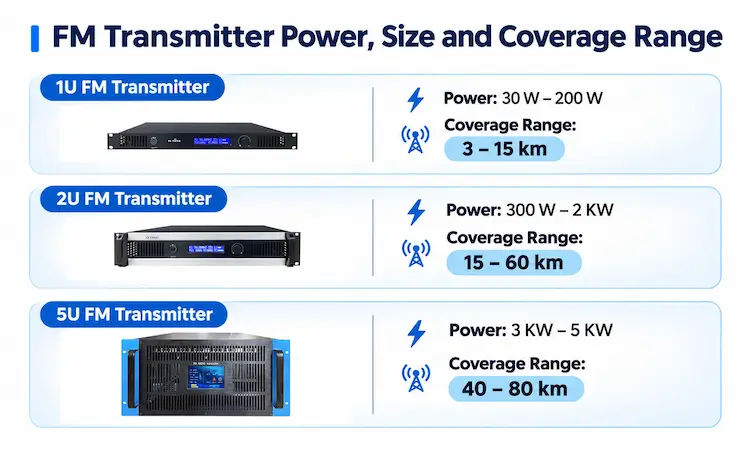
Typical causes
- Output power set too low
- Antenna mounted too low or obstructed by buildings, trees, or hills
- Cable loss that is higher than expected
- Mismatched antenna
How to fix it
- Verify the transmitter’s forward power reading against its rated output.
- Raise the antenna as high as practical and keep it clear of metal structures.
- Use low-loss coaxial cable, especially for long runs.
- Confirm the antenna is tuned to the operating frequency.
- Check that the power level is legal for your region.
Antenna height usually has a greater effect on coverage than a small increase in transmitter power.
2. High SWR (Standing Wave Ratio)
SWR measures how much transmitted power is reflected back from the antenna system. A high SWR means energy is not being radiated efficiently and can damage the output stage.
Typical causes
- Antenna not tuned to the operating frequency
- Damaged or water-contaminated coaxial cable
- Loose, corroded, or poorly crimped connectors
- Incorrect connector or adapter type
How to fix it
- Reduce power or switch off the transmitter before inspecting the system.
- Inspect all connectors for corrosion, looseness, or moisture.
- Test the cable with an SWR meter or antenna analyzer.
- Re-tune the antenna, or replace it if it is damaged.
- Aim for an SWR below 1.5:1 for normal operation.
Many modern transmitters include SWR protection, which reduces output power or shuts the transmitter down when reflected power is too high. If the protection activates repeatedly, treat it as a sign of an antenna or cable problem rather than a transmitter fault.
3. Transmitter Overheating
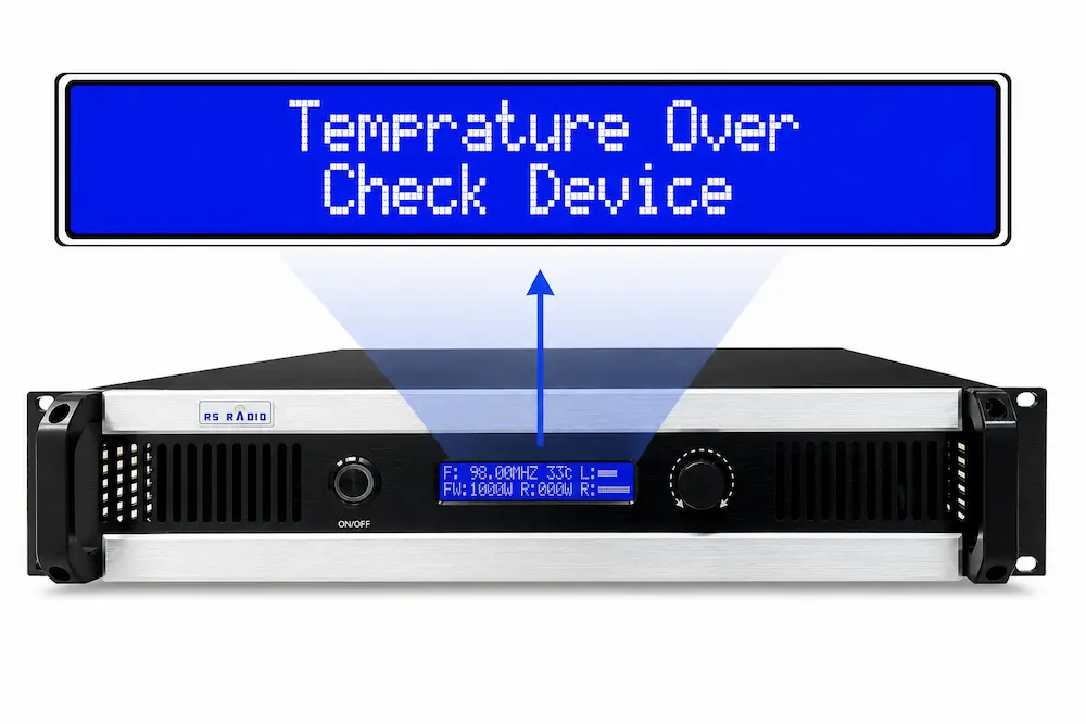
Heat is one of the main causes of reduced output and shortened component life. Some transmitters include thermal protection that reduces power or shuts down once the internal temperature reaches about 60 °C.
Typical causes
- Blocked vents or dust-clogged fans
- Insufficient room ventilation or high ambient temperature
- High SWR forcing the output stage to dissipate extra power
- Continuous operation at maximum power in a poorly cooled rack
How to fix it
- Keep at least several centimeters of clearance around ventilation openings.
- Clean dust from fans, filters, and heat sinks on a regular schedule.
- Improve room ventilation or add air conditioning where needed.
- Check the SWR (see Problem 2) to rule out reflected power as the heat source.
- Operate below maximum rated power if the site is hot.
4. Hiss and Background Noise
Typical causes
- Weak signal at the receiver, which makes receiver noise audible
- Audio input level set too low, so the audio chain must be boosted later
- Poor shielding or low-quality audio cables
- Electrical noise from nearby equipment such as dimmers, motors, or switching power supplies
How to fix it
- Set audio input levels correctly at the source instead of boosting them later.
- Use shielded, balanced audio cables.
- Keep audio and power cables separated.
- Move the transmitter and antenna away from noisy electrical equipment.
- Improve coverage if the problem occurs only at the edge of the service area.
5. Distorted Audio and Over-Modulation
Typical causes
- Audio input level too high
- Excessive gain or aggressive settings in the audio processor
- Clipping in the mixer or sound card
- Deviation exceeding ±75 kHz
How to fix it
- Lower the mixer or sound card output until peaks stay within range.
- Use an audio processor or limiter to control peaks.
- Check the transmitter’s modulation or deviation meter.
- Check pre-emphasis settings (50 µs or 75 µs depending on region) and make sure they match the processor.
- Test with a known clean audio source to isolate the problem.
6. Interference from Adjacent or Co-Channel Stations
Typical causes
- Operating frequency too close to a strong station
- Frequency drift
- Overloaded receivers near a high-power transmitter
How to fix it
- Scan the band at the listening location and choose the cleanest frequency.
- Leave at least 400 kHz of separation from strong local stations where possible.
- Verify the transmitter’s frequency stability and PLL lock indicator.
- Reduce power or adjust antenna direction to limit overlap with other signals.
7. Harmonics and Spurious Emissions
Typical causes
- Missing or inadequate low-pass filter
- Output stage overdriven
- Poor shielding or grounding
How to fix it
- Install a low-pass filter between the transmitter and the antenna.
- Measure harmonics with a spectrum analyzer.
- Reduce drive level if the output stage is overdriven.
- Check grounding and the shielding of cables and enclosures.
Spurious emissions can interfere with other services, so compliance with local regulations should be verified.
8. Hum and Buzz in the Audio
Typical causes
- Ground loops between equipment on different power circuits
- Unbalanced audio connections over long cable runs
- Power cables running alongside audio cables
How to fix it
- Power all studio and transmitter equipment from the same grounded circuit where possible.
- Use balanced XLR or TRS connections for long runs.
- Add an audio isolation transformer if a ground loop persists.
- Keep power and audio cables apart, crossing at right angles if they must cross.
- Check that the transmitter chassis is properly grounded.
9. Multipath Distortion and Signal Fading
Multipath occurs when the signal reaches the receiver via several paths, such as direct and reflected, causing distortion or fluctuating signal strength.
Typical causes
- Reflections from buildings, hills, or metal structures
- Antenna placed close to large reflective surfaces
- Mobile reception in urban areas
How to fix it
- Move the antenna to a position with a clearer line of sight.
- Adjust antenna height and orientation, and test in several locations.
- Consider the polarization (horizontal, vertical, or circular) used by your listeners’ receivers.
- Use a directional antenna to reduce energy sent toward strong reflectors.
10. Poor Stereo Reception or Missing RDS
Typical causes
- Stereo encoder disabled or incorrectly configured
- Low or excessive pilot tone level (19 kHz)
- RDS injection level set too low or too high
- Weak signal, which makes receivers switch to mono
- Wrong MPX input level
How to fix it
- Confirm that the transmitter or external stereo encoder is set to stereo mode.
- Verify the pilot tone is typically around 8-10% of total deviation.
- Adjust the RDS injection level, typically 2-4 kHz deviation.
- Check the MPX input level if an external processor or encoder is used.
- Test with several receivers, as sensitivity differs between models.
Recommended Troubleshooting Sequence
- Audio source: check levels, cables, and clipping.
- Processor and encoder: confirm stereo, pre-emphasis, and MPX settings.
- Transmitter: check power, frequency lock, temperature, and alarm indicators.
- Filters and cable: inspect connectors, test cable loss, and verify filters.
- Antenna: measure SWR, check mounting, height, and condition.
- Receiving location: test with more than one receiver and at several points.
Preventive Maintenance Checklist
- Record forward power, reflected power, and temperature regularly to spot trends.
- Clean fans and vents at scheduled intervals.
- Inspect and weatherproof outdoor connectors.
- Check antenna and tower hardware after storms.
- Keep a spare set of connectors, fuses, and a test cable on site.
- Document settings after any adjustment so that changes can be reversed.
Summary
Most FM signal problems fall into a few categories: antenna system faults (SWR, cable, connectors), thermal issues, audio level errors, and frequency or filtering issues. Working through the signal chain in order, from audio source to antenna, and measuring at each stage makes the cause easier to isolate. Protection features such as overheat and SWR protection help prevent damage, but repeated activation should be treated as a symptom to investigate rather than ignored.
Related Articles
3 Things to Consider Before Buying an FM Broadcast Transmitter
Choosing the right FM broadcast transmitter is an important decision when building a new radio station or upgrading...
Read more
High Power FM Transmitter: Everything You Need to Know
High Power FM Transmitter: Everything You Need to Know I work as broadcast engineer at RS Electronics for...
Read more
Common Mistakes When Installing FM Transmitters
Common Mistakes When Installing FM Transmitters I work as installation engineer at RS Electronics for nine years installing...
Read more